+8613003178786
  sales@lingyufab.com



Sheet Metal Design for Manufacturing (DFM): 10 Common Mistakes and How to Avoid Them
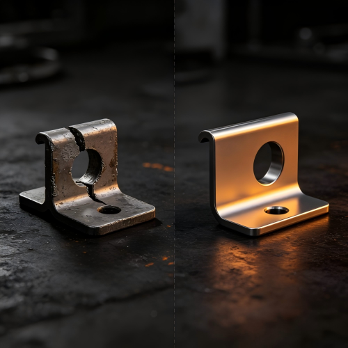
30
Jul’2026Sheet Metal Design for Manufacturing (DFM): 10 Common Mistakes and How to Avoid Them
Have you ever spent weeks perfecting a sheet metal design in CAD, only to receive parts that were warped, cracked, or didn't fit together in assembly? Or perhaps you have faced production delays, unexpected cost increases, or parts that simply couldn't be fabricated as designed? These are among the most frustrating and costly problems faced by design engineers, product developers, and procurement professionals. A design that looks perfect on screen can quickly become a nightmare on the shop floor.
The root cause of many such failures traces back to one thing: Design for Manufacturability (DFM) was not considered early enough. DFM is the practice of designing parts that can actually be produced efficiently using standard tooling and manufacturing processes. When DFM is applied early, it prevents errors before production starts, improves consistency across parts, and reduces costly rework. Early design review can significantly reduce part costs by eliminating unnecessary complexity and avoiding last-minute design changes—typically in the range of 20% to 40% depending on design complexity and production volume.
At Lingyufab, we bridge the gap between CAD models and real-world fabrication. Our engineering team performs free DFM reviews on every project. With over 20 years of precision manufacturing experience since 2003 and certification as a core supplier for Mitsubishi Electric, we have seen the same design mistakes repeated time and again. This guide highlights the ten most common sheet metal design mistakes we encounter and provides practical solutions to help you design parts that are easier to produce, more cost-efficient, and reliable in production.
Why DFM Matters in Sheet Metal Fabrication
Designing for sheet metal isn't like designing for plastic, castings, or 3D printing. It comes with its own set of constraints—bend allowances, grain direction, tool clearances, and flat pattern geometry. All of these considerations directly affect how a part is formed, cut, and assembled. Ignoring these details can lead to production slowdowns, material waste, or quality issues.
In sheet metal fabrication, small design choices have big consequences. A misplaced hole, an overlooked bend radius, or a tolerance that's too tight can stall production or drive up costs. The cost of fixing a problem during production is exponentially higher than catching it during the design phase. This is why Lingyufab provides free DFM reviews before production begins. Our goal is to catch issues early so you don't pay for them later.
Mistake 1: Submitting a 3D Model Without Proper Bend Information
Many designers submit solid 3D models without clearly defining bend lines, bend radii, or bend directions. Manufacturers may not be able to accurately identify bend locations, flat pattern dimensions, or forming sequences, leading to inaccurate quotations, dimensional deviations, or even manufacturing failure.
Solution: Use dedicated sheet metal modeling tools when creating the design. Clearly define bend lines, bend radii, and bend directions in your drawings. Keep material thickness consistent throughout the part and provide flat pattern drawings for fabrication and bend verification. Lingyufab's engineering team can review your 3D models and 2D drawings to identify missing or ambiguous information before production begins.
Mistake 2: Ignoring Bend Radius and Springback
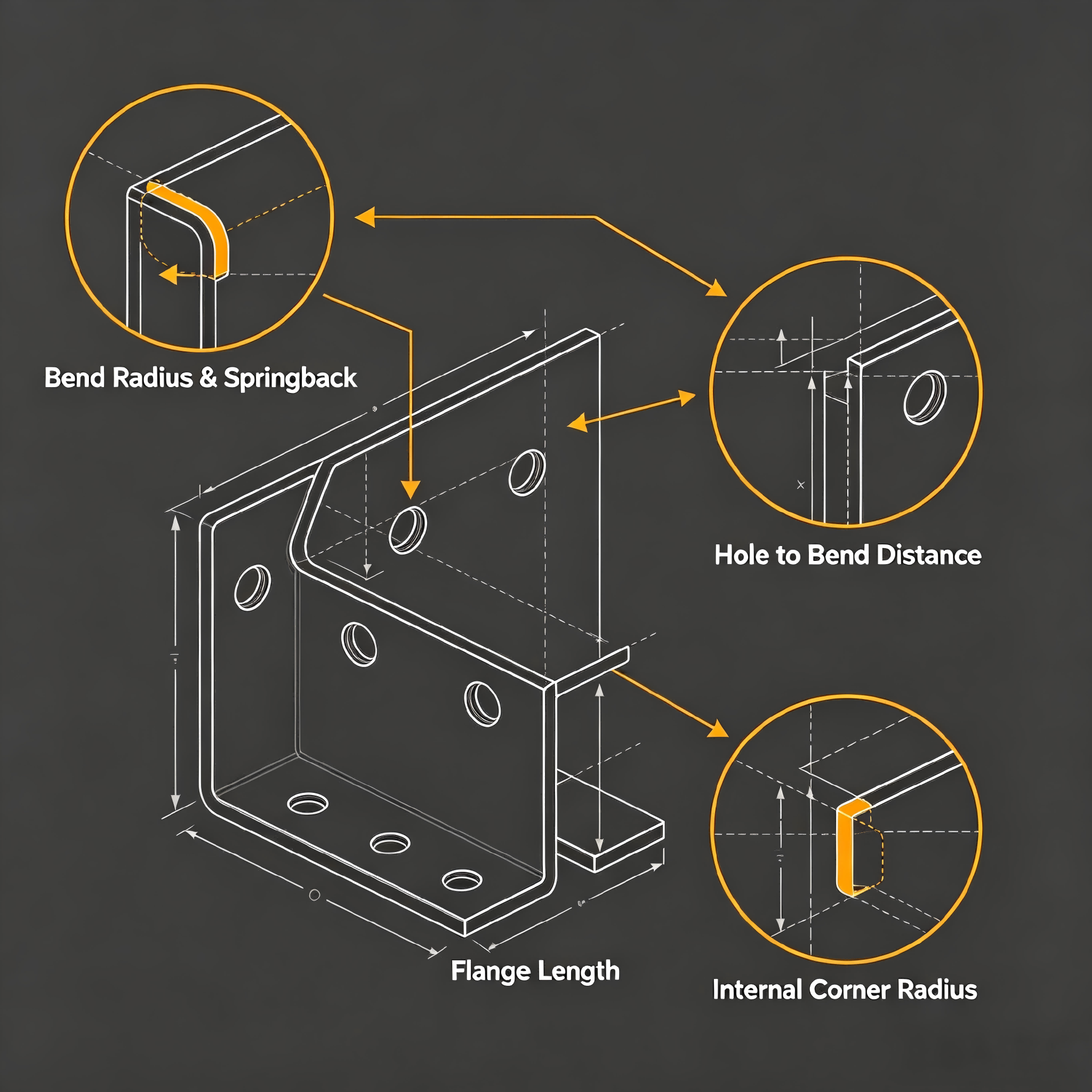
Bend radius is one of the most commonly overlooked design parameters. When the inside bend radius is too tight relative to the material thickness, the material can crack, stress fractures can occur, or the part can lose structural integrity. Springback occurs when the metal attempts to revert to its original flat shape after being bent. The extent of springback varies by material—aluminum alloys may spring back by 2–3 degrees, while high-strength steels can spring back by 5 degrees or more depending on thickness and bend radius.
Solution: A commonly used guideline is to match the inside bend radius to the material thickness. For example, a 2mm stainless steel sheet typically works well with a 2mm inside radius. If you must use a tighter radius, check with your fabricator first. To compensate for springback, designers often add a small overbend so the part ends up at the correct angle. Use consistent bend radii throughout the same part to reduce tooling changes and manufacturing cost. Lingyufab's engineering team can recommend the optimal bend radius and springback compensation for your specific material and application.
Mistake 3: Placing Holes or Features Too Close to Bend Lines
This is one of the most common and costly design mistakes. Material near the bend area undergoes severe deformation during bending. Holes, slots, or cutouts placed too close to a bend line can become distorted, crack at the edges, or lose structural strength. Even a hole placed correctly in the flat pattern can end up oval or misaligned after bending.
Solution: A widely accepted guideline is the 4T rule: maintain a minimum distance from the feature edge to the bend line of at least 4 × material thickness. As a general recommendation, place holes at least 2–3 times the material thickness away from any bend. If the feature cannot be relocated, add relief slots or cutouts to absorb the deformation. Lingyufab's DFM review identifies hole-to-bend conflicts early and provides specific relocation or relief recommendations to maintain part integrity.
Mistake 4: Missing Bend Relief Slots
When a bend line intersects directly with an edge, the material lacks enough space to deform properly, often causing tearing, bulging, or bend angle distortion. This is especially common in enclosures with bends near corners.
Solution: Add bend relief slots or cutouts at bend terminations. A common recommendation is that relief width should be at least the material thickness; relief depth should be at least the material thickness plus the bend radius. Relief slots help reduce stress concentration, improve corner quality, and improve part accuracy. Lingyufab's engineering team can suggest the right relief geometry for your design during the free DFM review.
Mistake 5: Designing Flanges That Are Too Short
Press brake tooling requires adequate support during bending. Extremely short flanges may slip, deform, or fail to maintain proper bend positioning. Short flanges simply can't span the die and punch, making bending unfeasible.
Solution: A generally recommended minimum flange length is at least 2 × material thickness + bend radius. Thin aluminum and thick stainless steel may require different minimum values depending on tooling capability. If extremely short bends are unavoidable, consider replacing them with welded or riveted assemblies. Lingyufab's experienced operators and comprehensive tooling inventory allow us to handle a wide range of flange lengths—but we will always flag designs that may present challenges.
Mistake 6: Overlooking Bend Sequence and Collision Risks
Closely spaced bends or conflicting bend directions can create part interference or tooling collisions during forming. Long flanges and narrow channels often cause parts to hit the machine's punch or other tooling, halting the process.
Solution: Maintain sufficient spacing between bends for tooling clearance. Simulate the bend sequence for complex parts. Follow common forming practices such as "inside bends first, outside bends later". If necessary, split enclosed box structures into multiple parts. Adding a parallel edge for support helps the part maintain its intended shape and alignment during bending. Lingyufab's engineering team sequences bends to minimize distortion—and when we review your design, we can identify potential collision risks before they become production problems.
Mistake 7: Ignoring Hole Size and Spacing Guidelines
Holes that are too small for the material thickness can be difficult to cut cleanly. If holes are too close together, heat from laser cutting or stress from punching can cause distortion.
Solution: A commonly used guideline is to maintain a minimum hole size that is at least equal to the sheet thickness. For example, in 2mm stainless steel, holes smaller than 2mm may come out tapered or incomplete. A standard recommendation is to maintain an edge-to-edge spacing of at least 1.5 times the sheet thickness. In 3mm aluminum, this translates to keeping holes at least 4.5mm apart to help ensure clean edges and stable parts. If extruded holes are too close together it can lead to metal deformation; a general guideline is that the minimum distance between two extruded holes should be six times the thickness of the sheet metal. Lingyufab's in-house laser cutting and CNC bending capabilities allow us to achieve precise hole dimensions and spacing.
Mistake 8: Designing Sharp Internal Corners
Sharp internal corners can lead to stress points, cracking, or require special tooling. In sheet metal fabrication, a small radius adjustment often solves the issue and speeds up production.
Solution: A commonly recommended practice is to add a radius to internal corners—typically at least half the material thickness. The radius helps reduce stress concentrations, extends tool life, and helps prevent cracking during forming. Lingyufab's engineering team can recommend the optimal radius for your specific design during the free DFM review.
Mistake 9: Specifying Unrealistic Tolerances
Over-tolerancing a non-critical feature increases inspection time and slows down production unnecessarily. Tighter tolerances generally mean slower production, which can result in increased labor hours due to the need for greater precision.
Solution: When possible, avoid tight tolerances in sheet metal fabrication. Only apply tight tolerances to critical features. Use standard tolerances for everything else. Typical sheet metal tolerances are approximately ±0.1mm for laser cutting and ±0.5° for bending, though these can vary depending on material thickness and part geometry. Lingyufab's quality control procedures, backed by ISO 9001, ISO 14001, and TÜV CE certifications, ensure that standard tolerances are consistently met—and we will flag any tolerance requirements that may add unnecessary cost.
Mistake 10: Complex, Overcomplicated Part Geometry
Complex cutouts, overlapping bends, or excessive flange variation can reduce yield and increase machine time. Each additional bend, cutout, or feature adds cost and increases the chance of errors.
Solution: Simplify your design wherever possible. Reduce overall part dimensions if geometry allows. Eliminate internal pockets or holes that don't nest well. Avoid acute angles or complex cutouts. If possible, make sure all bends on the same plane go in the same direction—this allows the brake or press machine to perform the bend without having to reorient the part, which helps control costs. Lingyufab's engineering team can suggest simplification opportunities that reduce cost without compromising function.
DFM Checklist for Engineers and Procurement Professionals
Before sending your design to production, run through this quick checklist to catch common issues before they become expensive problems:
| Check Item | Guideline |
|---|---|
| Bend radius | ≥ 1 × material thickness (generally recommended) |
| Bend relief | Width ≥ material thickness; depth ≥ thickness + bend radius (typical guidelines) |
| Hole-to-bend distance | ≥ 4 × material thickness (4T rule) |
| Hole diameter | ≥ material thickness (generally recommended) |
| Hole-to-hole spacing | ≥ 1.5 × material thickness (typical guideline) |
| Flange length | ≥ 2 × material thickness + bend radius (generally recommended) |
| Internal corners | Add radius (≥ 0.5 × material thickness recommended) |
| Tolerance | Only apply tight tolerances to critical features |
| Bend direction | Keep all bends in same direction where possible |
Note: All values above are general design guidelines. Specific requirements may vary depending on material type, thickness, and application. Always consult with your fabrication partner for project-specific recommendations.
Where DFM Principles Apply Across Industries
Good design practices benefit every industry that uses sheet metal components:
Medical Devices — Designs for medical equipment must meet stringent cleanliness and corrosion resistance requirements. DFM principles help ensure that stainless steel enclosures are designed with proper radii and surface finish specifications to meet hygiene standards while remaining manufacturable. Lingyufab's quality control procedures, backed by ISO 9001, ISO 14001, and TÜV CE certifications, ensure that every part meets the highest standards.
Industrial Equipment — Industrial machinery demands high-strength components that withstand constant vibration and harsh conditions. Proper DFM ensures that mounting brackets, machine guards, and control cabinets are designed with appropriate bend radii and tolerances for reliable performance. Lingyufab has over 20 years of experience serving industrial equipment manufacturers.
Electronics and Telecommunications — Electronic enclosures require precise hole placement for PCB mounting and connector cutouts. DFM guidelines ensure that features are properly spaced from bends and that tolerances are realistic for production. Lingyufab's in-house laser cutting and CNC bending capabilities deliver the precision electronic applications demand.
Automotive and Electric Vehicles — Lightweight designs often use thinner materials that require careful DFM attention. Proper hole-to-bend spacing, bend relief, and springback compensation are essential for structural integrity. Lingyufab is a certified core supplier for Mitsubishi Electric, demonstrating our ability to meet the stringent quality standards of the automotive industry.
HVAC and Construction — Sheet metal components for HVAC and construction require durability and proper fit. DFM principles help ensure that ductwork and structural components are designed with appropriate tolerances and bend sequences for efficient fabrication and assembly. Lingyufab's integrated manufacturing process ensures consistent quality across large and small production runs.
How Lingyufab Can Help with Your DFM Needs
Lingyufab is a professional sheet metal fabrication manufacturer and supplier based in Shanghai, China, with over 20 years of precision manufacturing experience since 2003. We follow strict Japanese quality standards and are a certified core supplier for Mitsubishi Electric.
What sets Lingyufab apart is our commitment to engineering support and design optimization. Our experienced engineering team can review your drawings before production begins, identifying potential issues like tight tolerances that add cost without functional benefit, or features that are difficult to manufacture. We provide cost-saving solutions and design optimization to help you get the best possible part for your budget.
Our comprehensive in-house capabilities include:
Laser cutting — High-precision cutting for accurate flat patterns, clean edges, and minimal material waste
CNC bending — Precision bending with consistent accuracy across all parts and batches, with springback compensation programmed for each material and thickness
Welding — TIG welding for stainless steel, MIG welding for general fabrication, and spot welding for thin sheet connections
Assembly — Complete assembly of fabricated components into finished products and sub-assemblies
Surface treatment — In-house powder coating, anodizing, electroplating, and polishing
Fastener installation — Direct installation of our own manufactured SEMS fasteners, bolts, nuts, and self-clinching fasteners
One supplier, full responsibility. From laser cutting and CNC bending to welding, surface treatment, and fastener installation, we handle everything under one roof. This integration ensures consistent quality, shorter lead times, and a single point of accountability for your entire project.
If you are unsure whether your design is manufacturable, our engineering team is available to review your drawings and provide a free DFM consultation. We'll help you identify potential issues before production begins—saving you time and money.
Conclusion
Good sheet metal design balances function with fabricability. By following these DFM guidelines—using appropriate bend radii, respecting minimum hole-to-bend distances, adding bend reliefs, simplifying geometry, and specifying realistic tolerances—you can avoid costly mistakes, reduce production delays, and help ensure your parts are manufactured correctly the first time. Early collaboration with an experienced fabrication partner like Lingyufab can make the difference between a design that works on paper and one that works in production.
FAQs
Q1: What is DFM in sheet metal fabrication?
DFM (Design for Manufacturability) is the practice of designing parts that can be produced efficiently using standard tooling and manufacturing processes. It helps ensure that every design choice, from bend allowance to hole placement, supports smooth fabrication instead of creating problems on the shop floor.
Q2: Why is bend radius important in sheet metal design?
A bend radius that is too tight relative to the material thickness can cause cracking, stress fractures, or loss of structural integrity. A commonly used guideline is to match the inside bend radius to the material thickness, though this may vary depending on the specific material and application.
Q3: What is the 4T rule in sheet metal design?
The 4T rule states that the minimum distance from a feature edge (such as a hole or slot) to the bend line should be at least 4 × material thickness. This helps prevent distortion, cracking, and loss of structural strength during bending.
Q4: Can Lingyufab review my design before production?
Yes. Lingyufab provides free DFM review services. Our engineering team can review your drawings, identify potential manufacturability issues, and suggest design improvements that can help reduce costs and simplify production.
Q5: What file formats do you accept for design review?
We accept 3D files in STEP (.stp), IGS (.igs), and SolidWorks (.sldprt) formats, and 2D drawings in PDF, DWG, and DXF formats. If you don't have drawings, we offer reverse engineering services from physical samples.
Q6: How much can DFM review save on production costs?
Early DFM review can significantly reduce part costs by eliminating unnecessary complexity and avoiding last-minute design changes—typically in the range of 20% to 40% depending on design complexity and production volume. The earlier DFM is applied in the design process, the greater the potential savings. Lingyufab's free DFM consultation helps you capture these savings before production begins.