
 +8613003178786
 sales@lingyufab.com
5G Communication Module Housing Selection for Outdoor IoT
5G Communication Module Housing Selection for Outdoor IoT
Which housing properties decide whether an outdoor 5G gateway keeps its signal, stays dry, and survives a summer afternoon in direct sun? Most teams ask this after the first prototype fails a spray test. This guide shows how to specify a 5G communication module housing before prototype validation, so the first build is already close to the final design.
You start with a module datasheet, a PCB outline, and an installation site. You finish with a written housing specification covering ingress rating, material, antenna strategy, thermal path, sealing, and a test plan. If your module board also carries power or interface hardware, Custom Metal Components for communication and power modules show what is already manufacturable in sheet metal.
What to Gather Before You Specify Anything
Some inputs block the whole design. Others can be settled after the first prototype. Separate them early.
| Input | Why it matters | Blocks progress? |
|---|---|---|
| Module thermal dissipation (watts, from datasheet) | Sets how much heat the walls must carry | Yes |
| Antenna port count and connector type | Decides cutouts, bulkhead connectors, and sealing points | Yes |
| PCB outline, mounting holes, tallest component | Defines internal volume and standoff positions | Yes |
| Installation site and exposure | Drives IP rating, UV, and corrosion choices | Yes |
| Mounting method (pole, wall, cabinet) | Sets bracket design and load path | Yes |
| Color, logo, label area | Cosmetic only | No |
| Annual volume forecast | Affects tooling choices, not the first prototype | No |
If the module datasheet does not list dissipation under sustained transmit, ask the module supplier before going further. Every later step depends on that number.
Step 1: Classify Exposure Before Choosing a Rating
When Outdoor Ingress Ratings, UV Resistance, and Connector Sealing Become Mandatory
Not every installation needs full outdoor protection. Over-specifying adds cost. Under-specifying causes field returns. Use the table below to place your site, then confirm the rating against your own customer or regional standard.
| Installation condition | Ingress rating | UV resistance | Connector sealing |
|---|---|---|---|
| Indoor or inside a locked cabinet | Optional (dust control only) | Optional | Optional |
| Outdoors under a canopy, no direct rain | Mandatory, starting near IP54 | Recommended for gaskets and labels | Recommended |
| Wall or pole mount, rain and sun exposed | Mandatory, IP65 or higher | Mandatory for gaskets, plastic windows, cable jackets | Mandatory on every external port |
| Roadside, vehicle splash, pressure washing | Mandatory, IP66 jet test | Mandatory | Mandatory, with strain relief |
| Flood risk or temporary immersion | Mandatory, IP67 IoT enclosure | Mandatory | Mandatory, rated to the same level as the housing |
Why these thresholds. Dust and water enter at joints and penetrations, not through flat panels. Once a unit sees rain, every cable entry and antenna port becomes a leak path. UV matters because the metal rarely fails first. Silicone and EPDM gaskets, plastic radome windows, and cable jackets harden and crack under sun.
Limits. IP67 covers temporary immersion (1 m for 30 minutes under IEC 60529). It does not automatically include the powerful water jets of IP66. If the unit faces both jets and immersion, specify both ratings. A rating also applies only to the finished assembly with its connectors fitted, not to the empty box.
Step 2: Decide Where the Antennas Go
Metal blocks radio signals. A closed steel box around an antenna kills the link. Your 5G antenna enclosure design therefore starts with one of two choices.
External antennas on bulkhead connectors. The housing stays fully metallic and shielded. Best for gateways at fixed sites. Each connector needs its own O-ring or gasket seal.
Antennas behind a non-metallic window. A UV-stabilized plastic radome or cover sits over a cutout. Best for compact units. The window joint becomes a second seal and a second UV exposure point.
Checkpoint: bench-test throughput with the antenna in free air, then again mounted in the prototype. A large drop means the metal edge or the mounting location is interfering. Keep antennas clear of cutout edges and ground planes as the antenna vendor specifies. The most common mistake is placing the antenna at the end of the cavity closest to the heat sink because the space was free.
Step 3: Choose Material and Finish
| Material | Fits when | Limit |
|---|---|---|
| 304 stainless steel | General outdoor use, inland sites | Can stain near salt spray or de-icing chemicals |
| 316 stainless steel | Coastal, chemical, or washdown sites | Higher material cost than 304 |
| Aluminum | Heat spreading matters and weight is limited | Needs anodizing or coating for harsh sites |
| Carbon steel with powder coat | Cost-sensitive, moderate climates | Rust can start at scratched coating or cut edges |
Most outdoor 5G units we see specified fall between 304 stainless and coated aluminum. Choose 316 when salt or chlorides are in the environment description. Choose aluminum when the thermal budget is tight and the housing itself must spread heat.
Step 4: Build the Thermal Path, Seal, and Fastening Plan
Work through these in order, because each one constrains the next.
Route heat to the wall. Place the module's hottest component against a wall using a thermal pad or a machined pedestal. A sealed housing has no airflow, so the outer surface is the radiator. Add external fins or a heat dissipating enclosure assembly only if the wall area is insufficient.
Allow for solar load. A dark surface in direct sun adds heat on top of the module's own dissipation. A lighter finish or a sunshield reduces it.
Specify the seal. Use a continuous gasket in a groove or on a flat flange, with the compression range taken from the gasket supplier. Seam welds on the body should be continuous so no pinholes sit under the gasket.
Add a pressure vent if needed. Temperature swings pull moist air through weak seals. A membrane vent equalizes pressure without admitting water, and it reduces condensation.
Avoid extra leak paths. Use Custom Self-clinching Integrated Components or weld nuts instead of through-holes where the lid or mounting plate attaches. Blind threaded features keep the sealed volume closed.
Hold the flange flat. Gasket sealing depends on flatness. Our laser cutting, CNC bending, and TIG/MIG welding processes hold tolerances down to ±0.05mm on specified features. Weld distortion is still real, so call out the flange flatness requirement on the drawing and verify it.
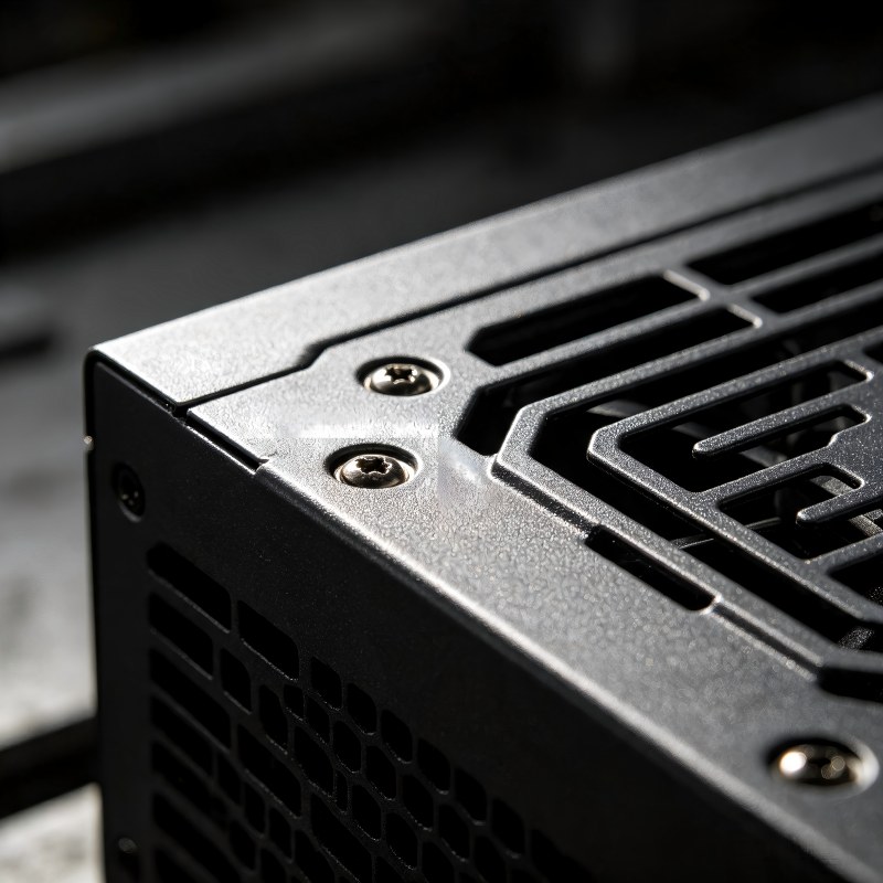
Mounting hardware is part of the seal story. Stainless flange bolts and matching weld nuts avoid separate washers, and a Custom Mounting Brackets design should keep load off the lid seal.
Step 5: Prototype, Test, and Recover From Failures
A 5G communication module housing should be tested at prototype stage, before tooling decisions. Our sample lead time is typically 7-10 days, with no minimum order for prototyping, so even a single piece is practical. See how Leading Sheet Metal Prototyping Manufacturer processes handle early revisions.
On the inspection side, we run 100% dimensional and visual checks before shipment and supply Mill Test Certificates for every material batch. As Quality Assurance Director, I look at flange flatness, hole position, and weld continuity first, because those three drive sealing results.
Completion check
The housing is ready for design freeze when all of these pass:
The PCB fits with clearance to all internal walls, and connectors align with cutouts.
A spray or immersion test at your target rating leaves no moisture inside (water indicator paper works well).
A thermal soak at maximum transmit stays below the module's rated temperature, with margin for solar load.
Throughput and signal strength inside the housing match free-air bench results within the limit you set.
Gaskets and plastic parts have a documented UV-stable material grade.
If a check fails, revisit this step
| Symptom | Likely cause | Go back to |
|---|---|---|
| Moisture at corners after spray test | Flange warp, gasket gap, or weld pinhole | Step 4, items 3 and 6 |
| Water at antenna ports only | Connector seal not rated to match the housing | Step 1 table, then Step 2 |
| Module throttles or resets in sun | No thermal path to wall, or solar load ignored | Step 4, items 1 and 2 |
| Weak signal inside the housing | Antenna too close to metal edge | Step 2 |
| Rust streaks after salt exposure | Material grade too low for the site | Step 3 |
Common mistakes to avoid
Rating the empty box instead of the finished assembly with cables and connectors.
Choosing IP67 and assuming jet resistance is included.
Skipping the pressure vent and then chasing condensation.
Using through-holes for lid screws that cut the seal.
Treating UV as a paint issue when gaskets and cable jackets age first.
Variations That Change the Procedure
Only a few variations alter the steps above.
Vehicle or machine mounting. Vibration and washdown push you toward IP66, locking fasteners, and strain-relieved connectors. Repeat Steps 1 and 4.
Cabinet-mounted units. If the housing lives inside a larger weatherproof cabinet, a lower rating may be enough, but check the cabinet's thermal limit. Our Custom Electrical Control Boxes show how internal modules are mounted in that case.
Multiple product variants. High-mix, low-volume programs benefit from one common body with different cutout plates, which keeps validated seals in place.
As an ISO 9001:2015 and ISO 14001 certified manufacturer and a Mitsubishi Electric certified core supplier, with over 20 years in sheet metal and fasteners, we build to your drawings under strict Japanese quality standards. For urgent revisions, 48-hour rapid delivery is available on selected orders.
Send your module datasheet, PCB outline, and target IP rating to our engineering team to request a quote and receive manufacturing feedback on your housing design.