+8613003178786
  sales@lingyufab.com



Sheet Metal Assembly Tolerances: A Practical Guide to Ensuring Parts Fit Perfectly
21
Aug’2026Sheet Metal Assembly Tolerances: A Practical Guide to Ensuring Parts Fit Perfectly
Have you ever received a batch of sheet metal parts that looked perfect individually, only to find during assembly that the holes didn't line up, the gaps were too wide, or the mating surfaces simply didn't meet flush? Or perhaps you have spent hours on the production line forcing parts together, only to discover that what should have been a simple assembly has become a costly rework project? These are among the most frustrating and expensive problems faced by design engineers, procurement professionals, and assembly managers. Parts that don't fit don't just slow down production—they create rework costs, delay delivery, and can even damage your reputation with customers.
At Lingyufab, we understand that assembly fit is the ultimate test of manufacturing quality. With over 20 years of precision manufacturing experience since 2003 and certification as a core supplier for Mitsubishi Electric, we have learned exactly what causes fit problems and how to prevent them. This guide explains the fundamentals of sheet metal assembly tolerances, the most common fit issues, and how to ensure your parts come together perfectly every time.
What Are Assembly Tolerances and Why Do They Matter?
In sheet metal fabrication, assembly tolerances are the allowable variations in part dimensions that still allow the final product to function and fit together correctly. Every manufacturing process has inherent variation—no two parts are ever exactly identical. Tolerances define how much variation is acceptable.
The challenge with sheet metal is that parts go through multiple processes: laser cutting, bending, welding, and finishing. Each step introduces its own variation, and these variations can accumulate—a phenomenon called tolerance stack-up. A laser cutter introduces a slight edge variation. Material thickness varies by a few thousandths from batch to batch. Each bend has its own angular deviation. By the time all these parts come together in assembly, small errors that were acceptable individually can combine to create a part that simply doesn't fit.
Why Sheet Metal Parts Don't Fit: The Root Causes
Understanding why fit problems occur is the first step to preventing them. Here are the most common root causes:
Tolerance Stack-Up
When multiple parts with their own tolerances are assembled, the variations add up. A bend that is 0.5° off on one part and another that is 0.5° off in the opposite direction might still be within individual tolerances, but together they create a cumulative error that prevents proper alignment. For parts with multiple bends in series, the total tolerance can stack to a much larger deviation than any single feature.
Unclear Datums and Reference Points
A datum is the reference surface or edge from which all measurements are taken. When datums are not clearly defined on drawings, different people measure from different starting points—and the parts don't match. The fabricator might measure from one edge while the assembly team measures from another, leading to parts that are technically "in tolerance" but still don't fit.
Missing Alignment Features
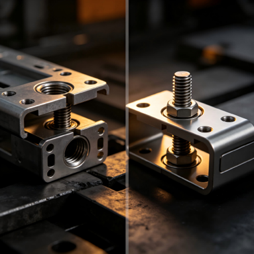
Parts that rely on manual forcing or visual alignment during assembly are prone to fit problems. Without clear alignment features—tabs, slots, or pilot holes—operators have no consistent way to position parts correctly during assembly. Tabs that are too loose or too tight are common early warning signs.
Inconsistent Material Properties
Sheet metal is not perfectly uniform. Material thickness varies within the same sheet and across different batches. Grain direction affects how the material bends and springs back. Residual stresses from the rolling process can cause parts to distort after cutting. A36 steel, for example, can vary in yield strength by 13% and still meet specifications. These variations are not errors—they are inherent properties of the material.
Incomplete or Incorrect Drawings
Drawings that lack proper tolerance specifications force the fabricator to guess. When critical dimensions are not clearly identified, or when general tolerances are not specified, the fabricator must make assumptions—and assumptions lead to mismatches.
Common Assembly Fit Problems and How to Prevent Them
Problem 1: Holes Don't Align
Misaligned holes are perhaps the most common and frustrating assembly problem. When mounting holes on two mating parts don't line up, the assembly either cannot be completed or requires significant rework.
What causes it:Hole position errors from laser cutting, cumulative bend errors that shift hole locations, or unclear datums that lead to inconsistent measurement.
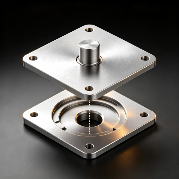
How to prevent it:Specify hole position tolerances clearly on your drawings. Use common datums for all measurements. Consider using slot holes instead of round holes for one set of holes to allow for adjustment during assembly. For critical mounting applications, the recommended practice is to oversize one hole in each mating pair to provide clearance for positional variation. Laser-cut holes can typically achieve ±0.005" to ±0.010" positional accuracy.
Problem 2: Flanges Don't Meet Flush
When bent flanges on mating parts don't align or leave gaps, the assembly looks unprofessional and may compromise structural integrity.
What causes it:Bend angle variations, springback that was not properly compensated, or inconsistent material thickness.
How to prevent it:Specify bend angle tolerances on your drawings—standard is typically ±1° for 90° bends, with precision grades achieving ±0.5°. Use consistent bend radii across mating parts to ensure predictable springback. Consider using a bend angle feedback system for critical applications.
Problem 3: Parts Are Warped or Twisted
Warped parts don't sit flat against mating surfaces, creating gaps and alignment problems.
What causes it:Residual stresses in the material, uneven heating during welding, or incorrect bend sequences.
How to prevent it:Specify flatness tolerances on your drawings. For critical applications, consider using leveled sheet metal to eliminate residual stresses. Control heat input during welding and use jigs to hold parts in position.
Problem 4: Tabs Don't Fit
Tabs that are too loose or too tight cause assembly problems—loose tabs don't guide parts properly; tight tabs require force and can damage the assembly.
What causes it:Inconsistent material thickness, incorrect bend allowances, or unclear tab geometry specifications.
How to prevent it: Specify tab dimensions with appropriate tolerances. Consider using standard tab sizes that are compatible with common material thicknesses. Use alignment features that provide guidance without requiring exact fit.
Problem 5: Cumulative Errors Cause Overall Assembly Shift
When multiple parts are assembled sequentially, small positional errors in each part can accumulate into a significant overall shift. For example, a mounting hole at one end of a long assembly might be within tolerance on each individual part, but the cumulative error across the entire assembly prevents bolts from passing through all the holes.
What causes it: Each part in the assembly has its own positional tolerance; when connected in series, these tolerances add together rather than cancel out. The resulting cumulative shift can be several times larger than the tolerance of any single part.
How to prevent it: Identify the critical alignment features early in the design process. Design the assembly so that tolerances cancel rather than accumulate—for example, by referencing all parts to a common datum rather than chaining tolerances from one part to the next. Use oversize or slot holes to absorb cumulative errors. For assemblies with multiple parts in series, specify a stack-up tolerance that accounts for the total expected variation, and consider adding adjustment features at key points to compensate for accumulated errors.
How to Specify Tolerances on Your Drawings
Good drawings are the foundation of good assembly fit. Here are practical guidelines:
Follow a Standard Tolerance System
Use a recognized standard like ISO 2768-m (medium) for general tolerances on unspecified dimensions. This provides a clear baseline that both you and your fabricator can reference.
Identify Critical Dimensions
Not all dimensions are equally important. Identify Critical-to-Quality (CTQ) dimensions that directly affect assembly fit and function. Apply tighter tolerances only to these critical features. Use standard tolerances for everything else.
Build a Datum Scheme
Define clear datums for each part. A datum is a reference surface or edge from which all measurements are taken. Every dimension on your drawing should reference these datums. This ensures that everyone—designer, fabricator, quality inspector, and assembly team—measures from the same starting point.
Use GD&T for Complex Features
For complex assemblies, consider using Geometric Dimensioning and Tolerancing (GD&T) to specify feature relationships. GD&T communicates functional requirements more precisely than simple plus/minus tolerancing. It tells the fabricator not just what size a hole should be, but where it should be and how it relates to other features.
Account for Cumulative Tolerances
When designing mating parts, always consider tolerance stack-up. If two parts each have a ±0.5mm tolerance on a critical dimension, the total variation at assembly is ±1.0mm. Provide sufficient clearance to accommodate this cumulative variation. For parts requiring high-precision assembly, consider secondary CNC machining after sheet metal fabrication.
How Lingyufab Ensures Assembly Fit
Lingyufab is a professional sheet metal supplier and fabrication manufacturer based in Shanghai, China, with over 20 years of precision manufacturing experience since 2003. We follow strict Japanese quality standards and are a certified core supplier for Mitsubishi Electric.
What sets Lingyufab apart as a sheet metal supplieris our systematic approach to assembly fit. We don't just make parts—we ensure they work together. Our engineering team reviews your drawings before production, identifying potential fit issues—unclear datums, missing alignment features, or tolerance stack-up risks. We confirm that all critical dimensions reference clear datums, evaluate cumulative tolerances, and recommend adjustments to ensure parts will fit together as intended.
Our comprehensive in-house capabilities include:
Laser cutting — High-precision cutting with consistent accuracy, ensuring hole positions and part contours are accurate from the start
CNC bending — Precision bending with consistent bend angles and springback compensation programmed for each material and thickness
Welding — TIG welding for stainless steel, MIG welding for general fabrication, and spot welding for thin sheet connections, with jigs and fixtures to prevent distortion
Assembly — Complete assembly of fabricated components into finished products and sub-assemblies, with fit verification before shipment
Surface treatment — In-house powder coating, anodizing, electroplating, and polishing, with thickness control to maintain critical dimensions
Fastener installation — Direct installation of our own manufactured SEMS fasteners, bolts, nuts, and self-clinching fasteners
One supplier, full responsibility. From laser cutting and CNC bending to welding, surface treatment, and assembly, we handle everything under one roof. This integration eliminates the coordination gaps that often cause fit problems when working with multiple suppliers.
If you are concerned about assembly fit in your sheet metal parts, our engineering team is available to review your drawings and provide a free tolerance analysis. We'll help you identify potential fit issues before production begins. If you are looking for a reliable sheet metal supplier, please don't hesitate to contact us.
Conclusion
Assembly fit is the ultimate test of sheet metal quality. Parts that don't fit create rework, delays, and customer dissatisfaction. But fit problems are preventable with proper design practices—clear datums, realistic tolerances, alignment features, and tolerance stack-up analysis. By following these guidelines and working with an experienced partner like Lingyufab—who combines precision manufacturing, engineering support, and integrated assembly capabilities—you can ensure your parts come together perfectly every time.
FAQs
Q1: What is tolerance stack-up in sheet metal assembly?
Tolerance stack-up is the cumulative effect of individual part tolerances on overall assembly fit. When multiple parts each have their own variations, these variations can add together to create a total deviation that exceeds acceptable limits. For sheet metal assemblies, this is particularly important because parts go through multiple processes—cutting, bending, welding—each introducing its own variation.
Q2: What is the typical tolerance for laser-cut holes?
Laser-cut holes typically achieve ±0.005" to ±0.010" positional accuracy. The specific tolerance depends on material thickness, part geometry, and the capabilities of the fabricator's equipment.
Q3: What is the typical tolerance for bend angles?
Standard bend angle tolerance is typically ±1° for 90° bends. Precision bending can achieve ±0.5° with well-maintained equipment and optimized parameters. Always specify bend angle tolerances on your drawing and discuss your requirements with your fabricator.
Q4: What is a datum and why does it matter?
A datum is a reference surface or edge from which all measurements are taken. When datums are not clearly defined, different people measure from different starting points—and the parts don't match. Clear datums ensure consistent measurement from design to production to assembly.
Q5: How can I prevent hole misalignment in sheet metal assemblies?
Specify hole position tolerances clearly, use common datums for all measurements, and consider using slot holes instead of round holes for one set of holes to allow adjustment during assembly. For critical mounting applications, oversize one hole in each mating pair to provide clearance for positional variation.
Q6: Can Lingyufab review my design for fit issues before production?
Yes. Lingyufab provides free design review and tolerance analysis. Our engineering team can review your drawings, identify potential fit issues, and suggest design improvements that ensure your parts will assemble correctly.