+8613003178786
  sales@lingyufab.com



Sheet Metal Defects and Prevention: A Practical Guide for Engineers and Buyers
30
Jul’2026Sheet Metal Defects and Prevention: A Practical Guide for Engineers and Buyers
Have you ever received a batch of sheet metal parts that looked fine at first glance, only to discover during assembly that they didn't fit, the bends were wrong, or the surfaces were scratched beyond repair? Or perhaps you have watched your production line grind to a halt because parts that should have been simple to make were warped, cracked, or dimensionally incorrect? These are not isolated incidents—they are the result of common defects that could have been prevented with better design, proper setup, and the right manufacturing partner.
At Lingyufab, we see these defects every day—and we know how to prevent them. With over 20 years of precision manufacturing experience since 2003 and certification as a core supplier for Mitsubishi Electric, our engineering team performs free Design for Manufacturability (DFM) reviews on every project. This guide covers the most common sheet metal defects, what causes them, and how to avoid them—so you can get parts that fit, function, and last.
Why Defects Happen in Sheet Metal Fabrication
Sheet metal defects are rarely caused by a single factor. They typically result from a combination of material properties, design choices, tooling selection, and process parameters. The good news is that most defects don't need expensive fixes—they just need better setup, smarter design, and a bit of prevention.
Understanding how defects form is the first step to preventing them. This guide walks you through the most common defects across bending, welding, cutting, and surface finishing—and shows you what to do about each one.
Bending Defects
Cracks and Fractures at the Bend
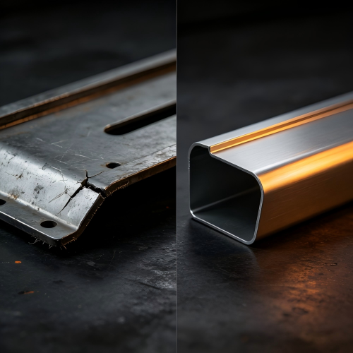
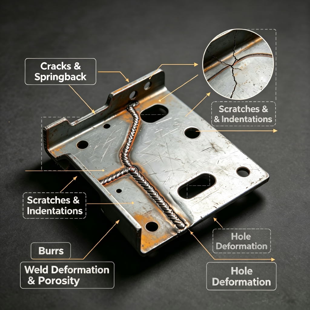
Cracking is one of the most common and costly sheet metal bending defects. It occurs when the tensile stress on the outer surface of the bend exceeds the material's elongation limit. Cracks almost always appear on the outside radius because that area undergoes the greatest stretching force.
What causes it: The most common cause is an inside bending radius that is too small for the material thickness, which overstretches the outer surface. Other causes include bending against the grain direction, using low-ductility materials like hard aluminum or cold-rolled steel, and over-bending without accounting for material limits. Edge cracking can also occur when laser cutting parameters were not optimized, creating a hardened heat-affected zone (HAZ) along the cut edge.
How to prevent it: Use a larger bend radius—a tight radius concentrates stress, and increasing the bend radius significantly reduces stress on the material. For mild steel, a V-die opening of approximately 8 × material thickness is recommended; for stainless steel, 10–12 × thickness; and for aluminum, 6–8 × thickness. Bend perpendicular to the grain direction whenever possible to minimize cracking. Switch to a more ductile alloy if your current material can't handle the pressure. And consider pre-heating or annealing metals that are prone to brittleness.
Springback
Springback is one of the most persistent and frustrating defects in sheet metal forming. It occurs when the material naturally tries to return to its original shape once the forming pressure is released. High-strength steels and aluminum alloys are particularly prone to springback—aluminum alloys may spring back by 2–3 degrees, while high-strength steels can spring back by 5 degrees or more depending on thickness and bend radius.
What causes it: Using the wrong die or punch angle, underestimating how stiff the material really is, and failing to account for the elastic recovery of the material.
How to prevent it: Overbend slightly—intentionally push past your target angle to let it "spring" into place. Use bottoming or coining dies to plastically deform the material and lock in the angle. Upgrade your tooling geometry to match the springback characteristics of your material. Run a few test bends—once you dial in the compensation, the results are consistently accurate. Springback isn't a defect you eliminate; it's one you learn to outsmart.
Wrinkling on the Inside Radius or Flanges
Wrinkling might not break the part, but it ruins the clean, professional look and can affect fitment in precision assemblies.
What causes it: Compressive forces bunching up material along the inside bend, flange length that is too long without proper support, and poor die design that doesn't control material flow during forming.
How to prevent it: Reduce flange length—long, unsupported flanges are prone to wrinkling. Use the right blank holder pressure and control material flow during forming. Choose the correct sheet thickness and apply lubrication to reduce stress. In severe cases, redesigning the tooling may be necessary.
Surface Defects
Scratches and Tooling Marks
Surface scratches are among the most visible and frustrating defects in sheet metal fabrication. They affect appearance and can become starting points for corrosion.
What causes it: Hard contact with the sheet surface from rough handling, dirty tools, abrasive particles, or improper handling. Tooling marks occur when tools are worn or not properly cleaned and lubricated.
How to prevent it: Keep all cutting and bending equipment clean and regularly maintained. Ensure operators understand how to handle material properly. Apply protective films on sheet metal prior to processing to provide a barrier against direct contact. Use proper die radii and apply lubrication to reduce friction. Light scratches can sometimes be fixed by polishing or finishing before the parts move further in production.
Denting and Indentations
Denting refers to localized depressions on the sheet metal surface caused by impacts or pressure.
What causes it: Accidental collisions during handling, overloading, or improper storage.
How to prevent it: Use flat supports when stacking materials and ensure cushioning between each sheet. Utilize professional tools and techniques to prevent accidental collisions or overloading during handling.
Warping and Distortion
Warping or distortion occurs when the sheet metal bends or twists out of shape during or after processing. It is one of the most common issues during bending.
What causes it: Uneven heating and cooling, especially during welding or other heat-related processes, or uneven internal stresses. Bending sequences that do not account for stress accumulation can also cause warping.
How to prevent it: Control the heat input during processes like welding and cutting—techniques such as preheating or post-weld heat treatment can help ensure more even temperature distribution. Perform bends that cause the least stress first to reduce accumulated internal stress. Use fixtures to hold the material in place during heating to reduce distortion. Choose materials with lower internal stress. Use pressure pads during bending to balance stress by applying counter-pressure to the material.
Cutting and Welding Defects
Burrs and Sharp Edges
Burrs are rough or sharp edges that occur during the cutting process, particularly with methods like shearing or laser cutting.
What causes it: Dull cutting tools, incorrect cutting clearances, or improper machine settings.
How to prevent it: Use well-maintained, sharp cutting tools—regular inspection and replacement prevent dull blades from creating burrs. Use post-processing techniques such as deburring or grinding to smooth out rough edges. Automated deburring tools or precision cutting methods can also reduce the likelihood of burr formation.
Welding Distortion and Warping
Welding introduces concentrated heat that can cause significant distortion in sheet metal parts, particularly in thin materials.
What causes it: Uneven heating and cooling during welding, excessive heat input, and insufficient fixturing to hold parts in position during welding.
How to prevent it: Control heat input during welding and use techniques such as preheating or post-weld heat treatment to ensure more even temperature distribution. Use fixtures to hold the material in place during welding. Ensure weld gaps are as small as possible—ideally less than 1/8". For thin sheets, consider using laser welding or other low-heat-input methods.
Design-Related Defects
Features Too Close to Bend Lines
Holes, slots, or cutouts placed too close to a bend line can become distorted, crack at the edges, or lose structural strength.
What causes it: Failure to account for material deformation during bending.
How to prevent it: Follow the 4T rule—maintain a minimum distance from the feature edge to the bend line of at least 4 × material thickness. Place holes at least 2–3 times the material thickness away from any bend. If the feature cannot be relocated, add relief slots or cutouts to absorb the deformation.
Sharp Internal Corners
Sharp internal corners can lead to stress points, cracking, or require special tooling.
How to prevent it: Always add a radius to internal corners—at least half the material thickness is recommended. The radius reduces stress concentrations, extends tool life, and prevents cracking during forming.
How Lingyufab Prevents Defects Before They Happen
At Lingyufab, we believe the best way to fix defects is to prevent them from happening in the first place. Our engineering team performs free DFM reviews on every project, identifying potential issues before production begins.
Our approach to defect prevention is systematic:
Design review — We review your drawings to identify potential manufacturability issues like tight tolerances, features too close to bend lines, or unrealistic specifications.
Material selection guidance — We help you choose the right material for your application—considering strength, ductility, corrosion resistance, and formability.
Process optimization — We select the right tooling, set up bend sequences to minimize distortion, and optimize cutting parameters to prevent edge hardening.
Quality control at every stage — We inspect at multiple stages—from raw material to finished product—ensuring defects are caught early, not after delivery.
Our comprehensive in-house capabilities include:
Laser cutting — High-precision cutting with optimized parameters to minimize heat-affected zone hardening and edge defects
CNC bending — Precision bending with springback compensation programmed for each material and thickness
Welding — TIG welding for stainless steel, MIG welding for general fabrication, and spot welding for thin sheet connections, with heat input carefully controlled
Surface treatment — In-house powder coating, anodizing, electroplating, and polishing
Assembly and fastener installation — Complete assembly of fabricated components, with direct installation of our own manufactured SEMS fasteners, bolts, nuts, and self-clinching fasteners
One supplier, full responsibility. From laser cutting and CNC bending to welding, surface treatment, and fastener installation, we handle everything under one roof. This integration eliminates the coordination gaps that often cause defects when working with multiple suppliers.
Quick Defect Prevention Checklist for Buyers and Engineers
Before sending your design to production, review this checklist:
| Check Item | What to Look For |
|---|---|
| Bend radius | Is the inside bend radius appropriate for the material thickness? |
| Grain direction | Are bends perpendicular to the grain direction? |
| Hole-to-bend distance | Are features at least 4 × material thickness from bend lines? |
| Bend relief | Are relief slots added at bend terminations? |
| Flange length | Are flanges long enough to be supported during bending? |
| Internal corners | Are radii added to internal corners? |
| Material selection | Is the material ductile enough for the required bends? |
| Tolerances | Are tolerances realistic—only tight on critical features? |
| Surface protection | Will protective films be used during processing? |
Conclusion
Sheet metal defects don't have to be inevitable. By understanding what causes cracks, springback, wrinkles, scratches, and distortion—and by taking proactive steps to prevent them—you can save time, reduce costs, and get parts that fit and function as intended.
Working with an experienced partner like Lingyufab—who combines rigorous DFM review, precision equipment, skilled operators, and integrated manufacturing—helps you avoid defects before they happen.
If you are concerned about potential defects in your sheet metal parts, our engineering team is available to review your drawings and provide a free DFM consultation. We'll help you identify risks before production begins.
FAQs
Q1: What is the most common defect in sheet metal bending?
Cracking at the bend is one of the most common defects. It usually occurs when the inside bend radius is too small for the material thickness, overstretching the outer surface of the sheet.
Q2: What causes springback in sheet metal bending?
Springback occurs when the material tries to return to its original shape after the forming pressure is released. High-strength steels and aluminum alloys are particularly prone to springback.
Q3: How can I prevent scratches on sheet metal parts?
Keep cutting and bending equipment clean, ensure operators handle material properly, and apply protective films on sheet metal prior to processing.
Q4: What is the 4T rule in sheet metal design?
The 4T rule states that the minimum distance from a feature edge (such as a hole or slot) to the bend line should be at least 4 × material thickness. This prevents distortion, cracking, and loss of structural strength during bending.
Q5: Can Lingyufab review my design to identify potential defects?
Yes. Lingyufab provides free DFM reviews. Our engineering team can review your drawings, identify potential manufacturability issues, and suggest design improvements that reduce defects and production costs.
Q6: What file formats do you accept for design review?
We accept 3D files in STEP (.stp), IGS (.igs), and SolidWorks (.sldprt) formats, and 2D drawings in PDF, DWG, and DXF formats. If you don't have drawings, we offer reverse engineering services from physical samples.